Advanced Application
Before diving into VPN, we just review some basic concept about static routing. This will be useful while doing network planning associated with VPN and the existing private network.
Network Gateway for Static Routing
Let’s start considering the machine with 2 Ethernet interfaces.
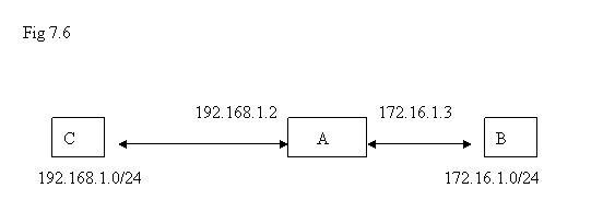
In the diagram, machine A is with 2 Ethernet interfaces with IP addresses 192.168.1.2 and 172.16.1.3 . It is sitting between the network 192.168.1.0/24 and 172.16.1.0/24 and it has the capability for forward the packets from one interface to another interface as long as the packets can reach to one of its ends. Machine B is sitting in the network 172.16.1.0/24 and machine C is sitting in the network 192.168.1.0/24 . If B issues a network packet with destination IP address of machine C, what kind of setting is needed for this packet to arrive C ?
Let’s assume there is no dynamic routing processes like RIP or OSPF involved; only static routing is used. The answer to the question above is that B needs to know if its packets want to go across the network to reach machine C, the routing table on B shall have the information that the “gateway” to destination 192.168.1.0/24 is 172.16.1.3 . Similarly, if network packet from C needs to reach B, it needs to have the knowledge that the “gateway” to the destination 172.16.1.0/24 is 192.168.1.2 .
Please just keep this simple concept in mind. The VPN described here is “routing-based” so that it needs this simple concept on many VPN applications after basic traffic tunnel is established.
The basic idea about VPN ( Virtual Private Network ) is to establish secured communication channel over the public network. The underlying mechanism we adopt is to create a “Virtual device with IP address” on the machines where VPN processes are running. Whenever a network application is trying to send packets into VPN, it just sends the packets into that “virtual device with IP address”. And it still uses the original routing mechanism on the machine to control where the packets should go on the basis of routing decision.
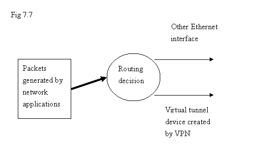
From the application level point of view, the high level network application will not aware of the difference of this virtual tunnel device created by VPN process; it is just being created as another network device although the “real traffic” still needs to use the “real network device”. But that work is hidden inside the tunnel. From higher application level, it can not see this.
We classify the usage of VPN into the following basic scenarios: client-to-site (mobile-to-site ) and site-to-site. They are explained as follows. We just quickly introduce the concept.
Client-to-Site ( or Mobile-to-Site )
One of the occasions for “client-to-site” application is: a site is protected by firewall that people inside the firewall can access the local machines or access the machines outside the firewall. But the firewall does not allow people from internet to access the machines inside the firewall freely. When a person brings his/her PC out of the office for business trip, he/she might want to use the PC as if it were in the office. “Client-to-Site” scenario can be applied to this situation by launching a VPN client program so that a virtual connection to the office can be established, and the rest of the software application can use this virtual connection to the office to fetch data. It is more than just “remote access” – a lot of programs can do remote access by encrypting the network packets in the public network ( like “https”, “ssh”, …. ). What we meant “virtual connection” here is that other application level programs can also use that “virtual connection” channel to transmit or receive data without any “special design” for using this communication mechanism as long as it is “normal” network applications by using TCP/UDP/IP .
The characteristics of “client-to-site” is that those “clients” do not have “fixed” public IP address; they might sit inside other offices’ firewalls or just using temporary public IP address. On the other hand, the “site” is with fixed public IP address so that “client” will know where to establish connection to the office.
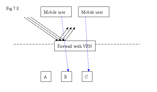
For those “mobile users” outside the firewall, when they use VPN client to enter the network inside firewall, they need to have “another class of IP addresses” as their identifiers encapsulated in the normal datagrams with those original IP addresses as identifiers outside. Otherwise, the firewall will block them by treating them as other non-authorized network connections from internet. Once those packets reach the other end of the VPN tunnel, their wrappers will be stripped by showing the IP address assigned by VPN and start the rest of the journey from there. This is the easy way to think how it works.
To give an IP address for each of those mobile PCs on this “Virtual Private Network”, the “site” server needs to know the class of IP addresses that it can allocate for the use for identifying VPN clients.
Since a mobile PC will get another IP address for use in VPN associated with the original IP address that has been used before launching VPN connection, another new interface with IP address assigned by VPN server will appear on VPN client side for this “client-to-site” scenario.
Thus, that “extra” new network interface represents the access to Virtual Private Network as we mention previously for introducing the underlying mechanism of VPN here.
From the Web GUI, the screens under VPN->Connection are all for “client-to-site” configuration.
In the screen VPN->Connection->Address Pool, the subnet specified there will be used for VPN application. IP addresses will be drawn from this pool to identify those VPN tunnel devices. Please notice that when you “turn on/off” VPN server process on this screen, it requires “reboot” if you are using “Enterprise version”. (SOHO version does not need “reboot” ). Due to this address pool, we can assign each mobile client with an IP address as the identifier used in VPN. Mobile users might not have public fixed IP addresses so that this approach is adopted. Once an VPN client has established successful connection with VPN server, it will obtain an IP address from VPN server so that the rest of the network applications can use this IP address to send/receive packets to/from VPN.
For VPN->Connection->Pushed Setting, please consider the following diagram:
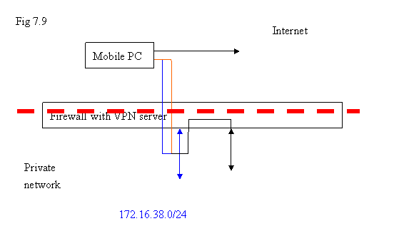
In this conceptual diagram, the blue line represents the network created by VPN processes. Inside the firewall, the original local network is 192.168.3.0/24. For mobile PC, it can just send the packets to the VPN virtual device on it. But what if the destination of the packets is located in 192.168.3.0/24 ? We have to make sure that packets generated from mobile PC will get into VPN at first.
So, when VPN client connects to VPN server, the server will push the route entry to the client by adding this information into its routing table so that destination with 192.168.3.0/25 will get into VPN. Similarly, the packets originated from the network 192.168.3.0/25 are intended to the hosts on VPN, if it can reach to the internal Ethernet interface of the firewall, it will be routed into VPN. The screen VPN->Connection->Pushed Setting is intended to entertain this purpose. Some other option like WINS server can be populated into clients via this method.
VPN->Connection->Key Generation is for encryption and authentication purpose. Certificate Authority ( CA ) will issue certificate to each VPN client along with key and certificate for VPN server and VPN clients through this generation process here. The Common Names indicated in each party should be unique. Please note that if the key and certificate are not generated successfully for VPN clients, the corresponding Common Name will be displayed as “empty” in the client configuration set list. It could be due to that the same name has been used before.
Please also notice that when you press “Remove” to delete a configuration set, if that configuration set has download and used in a VPN client, that VPN client still can use that set to connect VPN server. Thus, the safest method is to use “Purge” to delete everything ( including CA, Server key and certificate, and all configuration sets for clients ) and start everything over again.
The certificate issued currently is valid for 10 years since the date of generating the certificate. After the date is due, it is necessary to generate new certificates again. However, the admin people can just press “Purge” button to regenerate everything every month to ensure the keys to be updated frequently.
As Mobile Client
In VPN->Connection->Client File Download, there are two buttons over there: one is to download configuration file and other key files for VPN client so that it can connect to this VPN server; another button is to download VPN client program on Windows PC. So, on Windows PC, people can use the download VPN client program with the correct configuration to connect to VPN server. It just follows the similar procedure described in SOHO Admin guide.
For the machines running Azblink’s Linux, it is not necessary to download any client program. Only the package for keys and configuration file is enough. The package generated from other machine as VPN server can be uploaded via the screen VPN->Connection->As Mobile Client. Thus, the machine will turn out to be a VPN client and it can use the package to establish VPN connection to the VPN server.
It should be noted that each VPN client configuration set package shall be only used on one machine only in principle. The VPN server will try its best to assign the same IP address that the client first obtains while it connects to the VPN server first time to the same VPN client. This is especially important if you want to use VPN to fake fixed IP address for VPN clients on some applications.
( will provide more examples … )
Site-to-Site VPN
Site-to-Site VPN is used in the following occasion: both sides are with fixed public IP addresses and they are guarded with the program Border Control+VPN. We want to establish a channel between the two Border Control machines such that machines of private network on one side can go across this channel to access the machines on the private network of the other side.
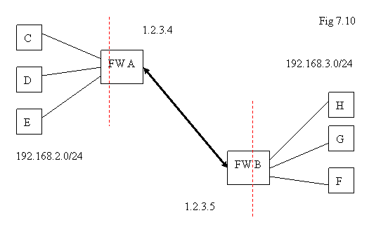
In the diagram above, we would like to configure Border Controls A and B such that machines C, D, E in the network 192.168.2.0/24 can go across the two firewalls to reach H, G, F in the network 192.168.3.0/24. Assume the two firewalls A and B are with fixed public IP addresses 1.2.3.4 and 1.2.3.5 respectively.
If we want to use “client-to-site” scenario to solve this question, every machine in C, D, E, H, G, F needs to have VPN client program installed to connect A or B. It is not efficient if there are many users and multiple platforms to support. It could be easier by just configuring the two machines A and B. This is why Site-to-Site scheme is come up for this kind of application.
The underlying mechanism for this is: it only needs to lock the two public IP addresses of A and B to establish the encryption pipe in the public network. Furthermore, some entries might be added into the routing tables on A and B so that traffic to the other location can be routed via this VPN encryption pipe. For the normal internet access, it is as usual without any changes.
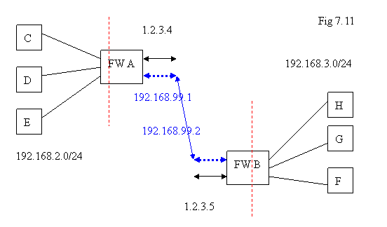
Similarly, a virtual device will be created by VPN process on A and B respectively. For each virtual network device, we just need to assign an IP address for it without conflicting with any existing IP address. In the diagram above, we just label it as 192.168.99.1 on A, and 192.168.99.2 on B. On the side A, if the network packets with destination in 192.168.3.0/24, we just route them via the interface 192.168.99.1; similarly, on the side B, if traffic are with destination in 192.168.2.0/24, we route them via the interface 192.168.99.2 .
In site-to-site scenario, we do not need to reserve a class of IP addresses to assign them as identifier in VPN; it is different from what we did for client-to-site.
Keys
By understanding this, it is easier to check with the VPN screens of site-to-site for configuration. VPN->Site-to-Site->Keys is for key generation. If you perform key generation on machine A, do not forget to bring the file set for “Remote” to machine B so that both sides can use “matched” files. When file sets are generated on one side, the other side has to use the file set generated from this side.
For site-to-site VPN, so far we only allow one “remote” location. Thus, you are only allow to generate one file set for remote use and the name of the file set has to appear as “client1”. Otherwise, you have to press “Purge” to re-generate everything from the beginning.
Network Setting
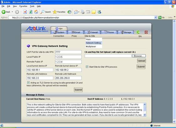
In the screen VPN->Site-to-Site->Network Setting, it only needs fill up the information as indicated in the diagram above; you do not have to worry about adding routing entry if the scenario is as described above; the system will handle that once you fill correct information on this screen. For the extra need of adding more routing entries, you can do it via System->Network->Static Routing.
Please notice that if you generate key file set on the machine, you need to check the box “Acting as TLS Server by using locally-generated CA and keys”. Otherwise, you need to upload the file set you obtain on the other end.
After you finish the setting on two sides, turn on “site-to-site” VPN process on both machines and reboot. And then, you can try “ping” from one side to the other and check if there is any response.
Let’s assume you generate all the keys on FW A. On FW A, you should set it as:
UDP Port: 7777
Local Public IP: 1.2.3.5
Remote Public IP: 1.2.3.4
Local tunnel device IP: 192.168.99.1
Remote tunnel device IP: 192.168.99.2
Remote LAN Address: 192.168.2.0
Remote LAN Netmask: 255.255.255.0
And click the “checkboxes” for “Acting as TLS server” and “Start site-to-site VPN process”.
On FW B, you should obtain the key from FW A and do upload that key. Besides that, the setting on FW B shall be set as
UDP Port: 7777
Local Public IP: 1.2.3.4
Remote Public IP: 1.2.3.5
Local tunnel device IP: 192.168.99.2
Remote tunnel device IP: 192.168.99.1
Remote LAN Address: 192.168.3.0
Remote LAN Netmask: 255.255.255.0
And DO NOT click the “checkbox” for “Acting as TLS server” so that it can act as “TLS client” .
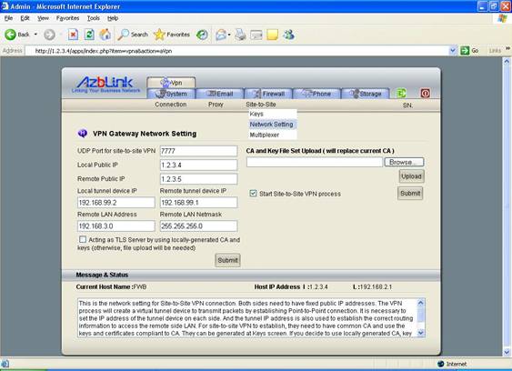
Upload the key file from FW A and click the box “Start site-to-site VPN process”. And then, reboot the machine.
Please notice that the UDP Port here for “site-to-site VPN” is indicated as “7777”. You also need to modify the firewall setting so that the firewall will allow the packets with destination UDP Port 7777 to be received. In the meanwhile, “mobile-to-site VPN” is using UDP Port 1194. They are using different UDP Ports as different instances. So, you can not mix those certificates or keys together.
As VPN Multiplexer
VPN Multiplexer is the term we use to indicate the following scenario:
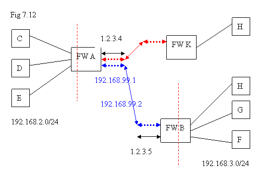
In the diagram above, FW A and FW B are connected via “site-to-site VPN” so that the LANs behind them can see each other; in the meanwhile FW A and FW K are also connected with “site-to-site VPN on another UDP port”. In this case, we say that FW A is as “VPN multiplexer”
The operation principle is that we have multiple instances of “site-to-site VPN” running on FW A with different UDP Ports. For adding extra instance of “site-to-site VPN” as “TLS server”, it can be done via VPN->Site to Site->Multiplexer. And you should use different UDP port, tunnel IP addresses, and different LAN address for the network inside FW K. On FW K, it needs to be configured as TLS client on the UDP port chosen by FW A.
The easy way to view this diagram is: from FW A, “red tunnel” is to FW K and “blue tunnel” is to FW B; “blue tunnel” is using UDP Port 7777 so that “red tunnel” should use different UDP Port.
Those are the “basic modes” of VPN provided in the Enterprise Server Package. It also allows the combination with different modes on one server. Currently, the following combinations of mixed modes are allowed on the same server:
| Mobile-to-site ( Server mode ) |
Mobile-to-site (Client mode ) |
Site-to-site |
| on |
on |
on |
| on |
on |
off |
| on |
off |
on |
| on |
off |
off |
| off |
on |
on |
| off |
on |
off |
| off |
off |
on |
| off |
off |
off |
When “site-to-site” VPN is turned on, you only can configure it as “TLS server” or “TLS client”. But “site-to-site TLS server” and “site-to-site TLS client” are not allowed to run on the same machine at the time of writing this document. And while running as “site-to-site TLS server” mode, you can have multiple instances running by using different UDP Ports. While using “site-to-site TLS client”, for simplicity’s sake, only one instance is allowed to run.
It should cover most of the basic application of VPN with the combinations of mixed modes. As a matter of fact, it is possible to configure a machine with “site-to-site TLS server” and “site-to-site TLS client” together on the same machine via console command line interface. But we try to avoid that in Web GUI; it would easily bridge the nodes that should not connect to each other or cause network address conflict while they are under different admin people or organizations.
We provide the following examples of network connection via VPN so that you might adapt them while doing network planning.
Example: Servers at different locations connecting to headquarter
You have several servers in different locations. Those servers can be accessed via some group of people; in the meanwhile, the servers have to send data to a central place.
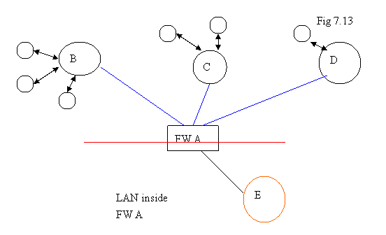
This is a scenario that would be used so often. Data sent via public network need to be encrypted. If the encrypted mechanism does not exist in the application itself, you can consider just send the data over VPN. Since the machine installed Azblink Enterprise Server package can act as “mobile-to-site client”, we can have the following network diagram:
In the diagram below, Server B, C, and D can be configured as “mobile-to-site VPN client” and firewall FW A can be configured as “mobile-to-site VPN server”. So, B, C, and D can access the super server E inside the firewall. However, the clients of B, C, D do not have the chance to follow the VPN link to trace E.
Example: Site-to-site VPN + Mobile-to-site VPN
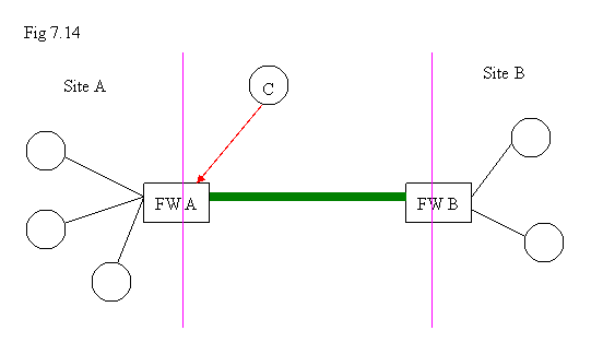
In the diagram above, everybody at Site A needs to access the machines located at Site B. So, FW A and FW B can set up a site-to-site VPN connection. In the meanwhile, some people traveling outside the office would like to connect back to their office at Site A. At this moment, a “mobile-to-site VPN server” can be started at FW A. Thus, FW A has two modes running: site-to-site VPN and mobile-to-site VPN server. |