Advanced
We designate the whole network into the following portions: net ( stands for the network outside firewall ), loc ( stands for the network inside the firewall ) and fw ( the firewall itself ). If VPN is used, “road” can be used to designate the network for VPN.
In general, we have some predefined rules that are not shown in the configuration screen for simplicity’s sake. Those rules are: all the traffic initiated from net destination to fw and loc are dropped; all the traffic from fw to net is accepted; all the traffic from loc to net is allowed.
Thus, when you add rules, you do not need to specify any rules to ACCEPT the traffic from loc to net or DROP the traffic from net to loc – those rules are predefined. All of these types of rules are predefined. The rules specified here are for “exception” cases. For example, we already know net to fw is dropped from those pre-defined rules, however, we just want to open TCP port 21 for telnet usage from net to fw. In this case, we can specify those exception rules as follows.
Add Rule
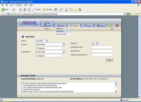
For each rule, we need to perform “action” on the network packets. Currently, those “actions” can be : ACCEPT, DROP, REJECT, DNAT, REDIRECT. In addition to those actions, For the attributes Source, Destination, Protocol, Destination Port, Source Port, Original Destination, they are used for identifying what type of network packets in the IP headers that we would like to perform the associated action on them. Source stands for “source IP address” in the IP header of the packets or the zones ( net, loc, fw) originating the network packets ; there are two choices for Protocol: UDP and TCP for IP traffic; Source Port and Destination Port stand for their corresponding fields in the IP header; Original Destination stands for the destination IP address field in IP header before the firewall action is applied on the packets. You can also use the IP address(es) you put into IP aliasing in Original Destination .
As for the attribute Destination, the usage of this attribute can be versatile. In the actions like ACCEPT, DROP, and REJECT, Destination stands for the zones ( net, fw, loc ) that the network traffic is going to. Thus, you can specify the rule like “ACCEPT” the traffic from “net” to “fw” associated with TCP port 23.
| Setting Entries on Page |
Valid data can be filled in the entry (example) |
| Action |
ACCEPT, DROP, REJECT, DNAT, REDIRECT |
| Source |
net, fw ,loc |
| Destination |
net, fw, loc, loc:192.168.1.22:80 , loc:192.168.1.2 , 3128 (port no) |
| Destination Port |
80, 1024: etc.. |
| Source Port:: |
- |
| Original Destination IP |
The IP of the traffic arrived at Port eth0. e.g. 1.2.3.4 |
| Protocol |
UDP, TCP |
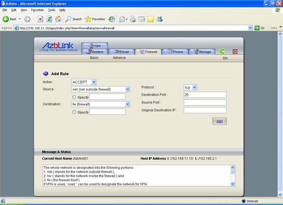
Example: Open the SMTP port on the firewall
Receiving emails usually uses SMTP at TCP port 25. Thus, we have the following setting in the firewall:
Action: ACCEPT
Source: net
Destination: fw
Protocol: TCP
Destination Port: 25
Example: Open the FTP port at the Border Control
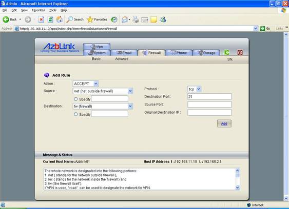
To transfer file (or file copy) among different machines, using FTP is the best choice. You have to open the TCP port 21 to allow this FTP service. At the firewall, the settings are followings:
Action: ACCEPT
Source: net
Destination: fw
Protocol: TCP
Destination Port: 21
In some cases, it also needs to open TCP port 20 for FTP. Please check FTP specification for details.
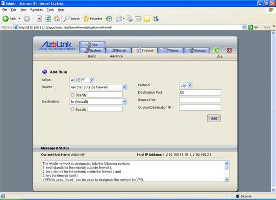
Example: Open the DNS port at the Border Control
To enable the DNS to serve the query from outside of Border Control, you need to open the UDP port 53. On the firewall, you need to have the following settings:
Action: ACCEPT
Source: net
Destination: fw
Protocol: UDP
Destination Port: 53
Example: Block Local Users to browse Internet ( http traffic )
Please notice that this firewall not only with the ability to block the outside traffic into the firewall, but also with the ability to block the traffic originating inside the firewall. For example, if you want to forbid all the internal users to use Web browser to view the Web sites outside the firewall, you can just do as follows:
Action: DROP
Source: loc
Destination: net
Protocol: TCP
Destination Port: 80
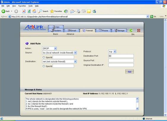
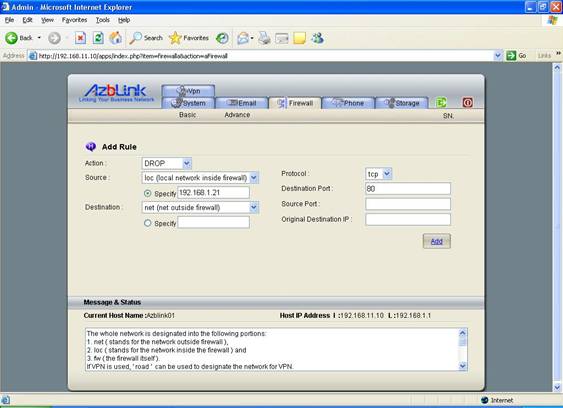
Then, all the outgoing traffic with destination TCP port 80 ( generic http traffic ) will be blocked. If you only want to block from a certain PC to use Web browser to access the websites outside the firewall, you can specify the IP address in Source. For example,
Action: DROP
Source: loc:192.168.1.21
Destination: net
Protocol: TCP
Destination Port: 80
This means: the host with IP address 192.168.1.21 can not browse Internet.
Example: Border Control with multiple IP addresses on eth0 – Port forwarding and IP aliasing
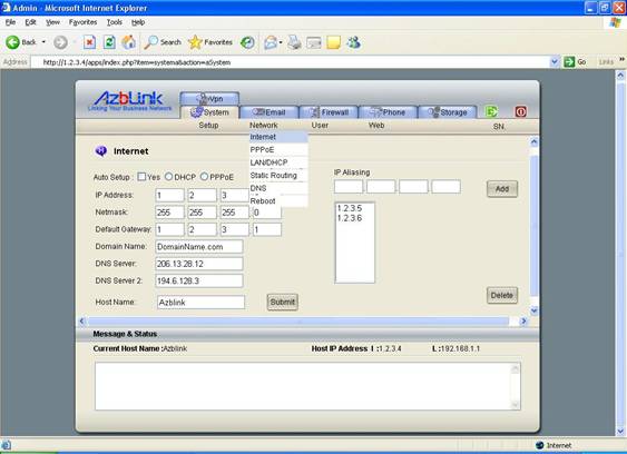
With IP aliasing introduced previously, we can have multiple IP addresses on eth0. Now, we would like to combine that feature with firewall here. What we are trying to do is to forward the traffic with different destination IP addresses to different internal servers ( even if they are with same destination ports ).
DNAT is the abbreviation of Destination Network Address Translation. It is used to change the fields associated with destination port and destination IP address in IP header of the packets. While DNAT is applied, the attribute Destination is of the format zone:IP_ADDRESS(:port_number ). For example, loc:192.168.1.22:80 stands for the traffic will be forwarded to the IP address 192.168.1.22 port 80, and the host with this IP address is located in zone LAN; another example loc:192.168.1.21 stands for the packets will be forwarded to 192.168.1.21 in LAN without changing the destination port.
DNAT is the basic operation for port forwarding. If you add some servers on the configuration screen for port forwarding, you will find out the corresponding DNAT rule show up in the configuration screen for listing rules. The following network diagram can be implemented by using DNAT and IP aliasing to forward the traffic to different servers according the original destination IP addresses:
We will use the following diagram to demonstrate how to use DNAT. The interface eth0 is with 3 IP addresses: 1.2.3.4, 1.2.3.5, and 1.2.3.6. And we have 3 internal servers A, B, C with IP addresses 192.168.1.2, 192.168.1.3, and 192.168.1.4 respectively.
We want to the packets with destination 1.2.3.4 TCP port 80 being forwarded to host A, packets with destination 1.2.3.5 TCP port 8080 being forwarded to host B, and packets with destination 1.2.3.6 TCP port 8081 being forwarded to host C.
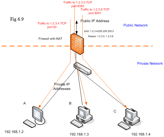
We can have setting as follows:
Action: DNAT
Source: net
Destination: loc:192.168.1.2
Protocol: TCP
Destination Port: 80
Source Port: -
Original Destination IP: 1.2.3.4
( forward the traffic to host A) ( Please notice the “-“ in the field Source Port )
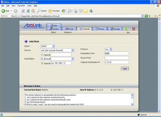
Action: DNAT
Source: net
Destination: loc:192.168.1.3
Protocol: TCP
Destination Port: 8080
Source Port: - (rember to enter “-“)
Original Destination IP: 1.2.3.5
( forward the traffic to host B)
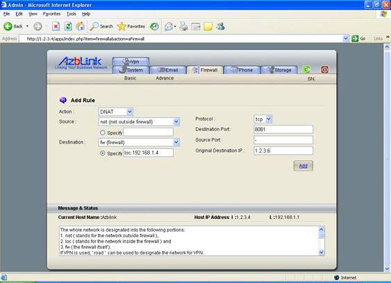
Action: DNAT
Source: net
Destination: loc:192.168.1.4
Protocol: TCP
Destination Port: 8081
Source Port: -
Original Destination IP: 1.2.3.6
( forward the traffic to host C)
Example: Redirect traffic from one port to another port
REDIRECT is to redirect certain type of traffic to the local port of firewall. In this case, Destination can only be port number.
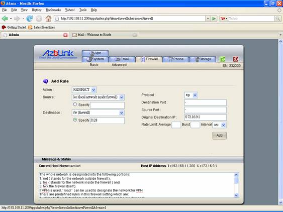
For example, the following will let the traffic from loc with original Destination Port 80 be redirected to the port 3128 :
Action: REDIRECT
Source: loc
Destination: 3128
Protocol: TCP
Destination Port: 80
Source Port: -
Original Destination IP: !172.16.9.1
At this place, “172.16.9.1” is the IP address of eth1. So, “!172.16.9.1” means “not equal to 172.16.9.1”. With this setting, your access to this machine via Web browser will not be redirected to port 3128, but the traffic to other destinations with destination port 80 will be redirected to port 3128.
It happens that TCP port 3128 is used by the Proxy Server along with our VPN product. So, it will force all the outgoing http traffic from local network to go through Web AP Proxy server first. Usually, this is needed for “Transparent Proxy”. We will have more discussion on that later.
Please note that you can not just forward to network traffic originally destined for one port to another port without any good reason. There must exist some processes listening to that port to process “redirected” traffic. Otherwise, if the “redirected” traffic are not handled by any process, it is natural that there would be no response associated with those “redirected” packets so that they will look like being dropped.
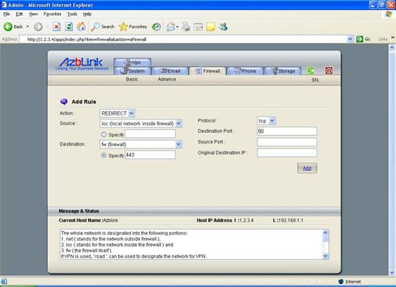
The following is a “meaningful example” by redirecting traffic destined for TCP port 80 to TCP port 443 so that “http” will turned out to be “https”: ( TCP port 443 is usually used by “https” )
Action: REDIRECT
Source: loc
Destination: 443
Protocol: TCP
Destination Port: 80
There are some more details when you add a rule into firewall. For example, for those attributes you do not care while processing network packets in firewall, you can just leave it as blank. But sometimes you will find out the fields you entered do not show up in the corresponding places because of “blank fields”. This is due to the internal processing logic of the configuration parameters while parsing those strings. In this case, you can just use “-“ to stand for “blank” to avoid confusion and let the rule be displayed correctly on the rule listing screen.
Please notice that “Port forwarding” and “LAN-NET loopback” will introduce some rules that are displayed in the rule listing screen. But it does not mean all the rules associated with “Port forwarding” and “LAN-NET loopback” are shown here. Some of the rules can not be represented in this format, and they are involved with more details on establishing the relationship of tracing network packets. That part is out of the scope of this document. It will be introduced elsewhere.
Delete Rule
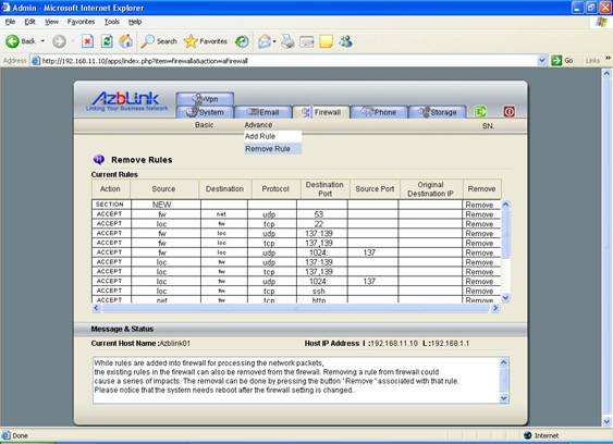
While rules are added into firewall for processing the network packets, the existing rules in the firewall can also be removed from the firewall. Deleting a rule from firewall could cause a series of impacts. The removal can be done by pressing the button “Remove” associated with that rule.
Please notice that the system needs reboot after the firewall setting is changed.
Issues on Instant Messengers
Blocking the traffic of Instant Messengers like MSN Messenger, Yahoo Messenger, AIM, ICQ, QQ or Skype or else seems a serious issue in some places. Here, we are not going to have a debate if this type of traffic should be blocked: some might argue that this kind of tools promote the communication between people; some might argue that this type of applications chew up the system resources ( network bandwidth, human concentration on work, or else… ), or in developing countries, bandwidth is very expensive and monopolized . To block it or not to block it, we are not going to provide answer here. We just briefly describe this type of traffic from Instant Messenger and leave the rest of the work to you on how to design your network with the available tools at hand.
In old times, NAT was not so popular so that some instant messengers would just let the two end-users to exchange directly after the sign-on processes on the mail servers. With the popularity of the deployment of NAT with firewall, those instant messengers were being developed with more sophisticated schemes for detecting the network topology or methods, e.g. the PCs are with “direct NAT” or using combining UDP or TCP packets to send out initial outbound messages, or establishing a lot of super nodes via some automatic mechanisms so that the rest of clients can have the initial node for starting communication…
Blocking those instant messengers mentioned above can not use “simple” schemes like by closing 4 or 5 ports or putting some IP addresses into “Blacklist” to block them. Some of those schemes might have worked initially, but it is not “Once-for-All” solution. Those Instant Messengers are evolving too. Nowadays, some of the Instant Messengers are scanning all the ports that can be used ( they even use TCP port 80 or 443 – that is originally reserved for http or https ) and encrypted the packets by using proprietary protocols. Moreover, even the target IP address for initial outbound connection is changing – it is a moving target. Some vendors just catch some signatures of certain Instant Messengers by doing traffic analysis and try to block them based on the live traffic collected. But as mentioned, this is not “once-for-all” solution.
So, how to block this type of traffic? We can think in this way: all the port numbers below 1024 are reserved for IANA ( Internet Assigned Numbers Authority – an organization for “number assignment” on Internet ). So, if an instant messenger is doing port scanning, it will scan the ports above 1024 at first, i.e. 1025 to 65535 .
Thus, block the outgoing traffic from loc to net with destination port above 1024 ( you can use “1024:” in the field destination port ). How about those instant messengers using destination port 80 or 443 ? Block all of the outgoing traffic from loc to net with destination port 80 or 443 ? You might say: this solution is not acceptable because you would like to use “http”; you do not want to block http traffic because of those instant messengers. This answer is: using http proxy and this http proxy has to be deployed on the firewall once you have those outgoing traffic blocked. And you have to force all of those stations inside the firewall to use Proxy. In other words, traffic from loc to net is not allowed – only some ports from loc to fw are allowed, and then fw to net by using Proxy.
What if some instant messengers are using TCP port 25 ( that is for email ) tomorrow ? If you really want to block that in a similar way, you have no choice other than putting email server on the firewall. Do you want to do that? That is network planning issue; you have to do the trade-off and think some other methods.
There are some other complicated scenarios that you can use once you understand the basic principles mentioned above. For example, you still can put “http Proxy” or “Mail server” on the machines inside firewall instead “on” the firewall if you allow only the machines for Mail server and http proxy can have the outgoing packets. For those planning and deployment issues, you also need to think about if it is easy to maintain the daily operation for flexibility or scalability of the network.
Furthermore, you might want to block all the outgoing UDP traffic. The simple idea is: block all traffic by default; if some people need to access outside, use proxy.
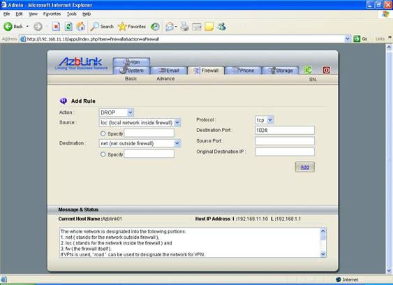
Example: Block all the outgoing traffic with destination TCP ports above 1024
Action: DROP
Source: loc
Destination: net
Protocol: TCP
Destination Port: 1024:
We will tell you how to do network planning for your office network at the end of this document. |