Internet
If the server has more than 1 Ethernet interface, the first Ethernet interface ( known as “eth0” ) will be designated as “Internet interface” that is used to connect to the outside network if the firewall is present. And the second Ethernet interface will be used to connect to the inside network ( known as LAN interface ) that is protected by the firewall.
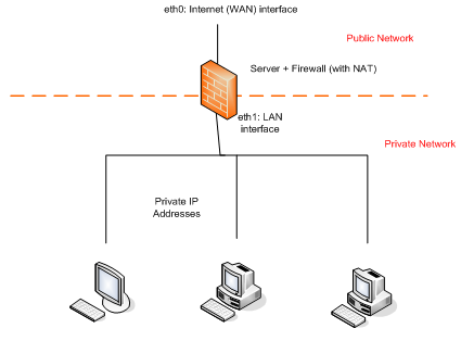
For the IP address of eth0 in the server, it shall be a fixed IP address for the other people to access this server without ambiguity. For the convenience of initial setup of the server from Web interface, we still provide the methods for fetching IP address automatically via DHCP client or PPPoE. The system is preset to launch DHCP client on the Ethernet interface eth0. Once the network is up for you to use the Web browser to access the server, you should disable “Auto setup” and specify the IP address.
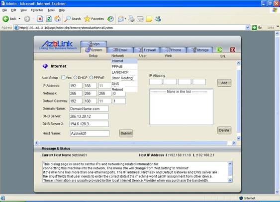
There are 3 options for "eth0" to get an IP address:
1. via DHCP client ( one of auto setup options )
2. via PPPoE ( one of auto setup options )
3. Static IP ( manually setting it )
You only can choose one of them. If PPPoE is used, DHCP client and Static IP will not be used; if Static IP is used, the other two will not be used.
When you select “Auto setup”, you also need to specify which method you would like to use to fetch IP address, e.g., DHCP client or PPPoE . Once DHCP or PPPoE is chosen, the system will ignore the rest of items like “IP Address”, “Netmask”, “Default gateway”, and DNS server in this menu. For DHCP, the parameters for IP address, netmask, default gateway, and DNS server will be obtained from DHCP server residing in the subnet that eth0 is listening to. As for PPPoE, it is necessary to fill in the corresponding data in the “PPPoE” page.
“IP Aliasing” is the feature such that one Ethernet interface can have multiple IP addresses. Usually, those multiple “aliasing” IP addresses should sit in the same subnet as the major IP address specified previously on eth0. It does not make sense that you specify an IP address that it does not belong to the subnet it resides unless your subnets are not well partitioned.
Here, we also quickly introduce the concept of “subnet” without going into too many details. For an IPv4 address, you usually see something like 61.2.34.56 or 192.168.1.34; actually, it stands for a 32-bit binary stream. For example,
1.2.3.4 → 00000001 00000010 00000011 00000100
61.2.34.56 → 00111101 00000010 00100010 00110100
Each “0” or “1” in the notation above is known as a “bit”. To know a group of IP addresses belonging to the same subset, you just perform bit-wise AND operation and check if the result is the same. If the result is the same, we say this group of addresses belonging to the same subnet. To explain what AND operation is, we just specify in the following manner:
0 AND 0 → 0
0 AND 1 → 0
1 AND 0 → 0
1 AND 1 → 1
IP Address 1.2.3.4 with netmask 255.255.255.0
00000001 00000010 00000011 00000100
AND ) 11111111 11111111 11111111 00000000
--> 00000001 00000010 00000011 00000000
( The result of AND operation is 1.2.3.0 . Sometimes, we just denote this subnet as 1.2.3.0/24 because there are 24 “1”s on the netmask. A valid netmask is with consecutive 1’s from the beginning. Thus, you do not have to worry about how to put those 24 1’s in those 32 positions. )
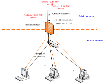
“IP Aliasing” can be combined with “Port Forwarding” feature in Border Control to distribute the traffic into several servers for processing. The features of Border Control will be introduced later.
PPPoE
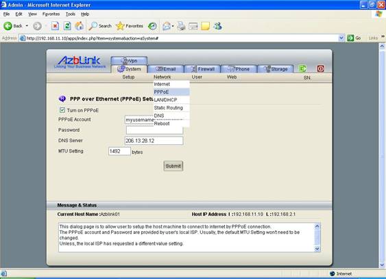
PPPoE stands for Point-to-Point Protocol over Ethernet. Usually, it is used by DSL service providers to control the access on their network. Usually, the MTU for Ethernet is 1500 bytes. But the PPPoE overhead plus two bytes of overhead for the encapsulated PPP frame implies the MTU of the PPP interface is 1492 bytes at most. To play safe, it would be better for the machines behind this server to have lower MTU values to go through this interface via PPPoE . The DSL service providers will give you the account and the Password so that you can enter the data on this page.
LAN/DHCP
The first Ethernet interface eth0 is known as the interface connecting to the outside network. The 2nd Ethernet interface eth1 is used to connect the local network. Sometimes, we just designate it as LAN.
It is also needed to have an IP address of this LAN interface. If DHCP server on this interface is turned on, the machines on that subnet can obtain their IP addresses from this server if they have DHCP clients running respectively. The IP addresses assigned to those machines will be in the range specified here. Please remember : on each subnet, there shall be only one DHCP Server running on it. If there are more than one DHCP servers running on the same network, you can not guarantee where the DHCP clients obtain their own IP addresses from a specific DHCP server. And usually, some other network settings are populated with DHCP. If there exist more than one DHCP servers on the same subnet, there might cause some impacts on the network setting of DHCP clients from fetching the wrong information from wrong server.
Fig 3.3
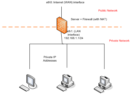
Example: Allocating IP addresses from LAN interface
Let’s use the diagram above as an example. If you click System->Network->DHCP/LAN, you set as follows:
IP Address: 172.16.9.1
Netmask: 255.255.255.0
Turn on DHCP Server (on)
Starting IP: 172.16.9.100
Ending IP: 172.16.9.200
Since DHCP server is turned up on the interface eth1, if host A, B, and C are with DHCP clients running respectively, each of them will obtain an IP address between 172.16.9.100 and 172.16.9.200.
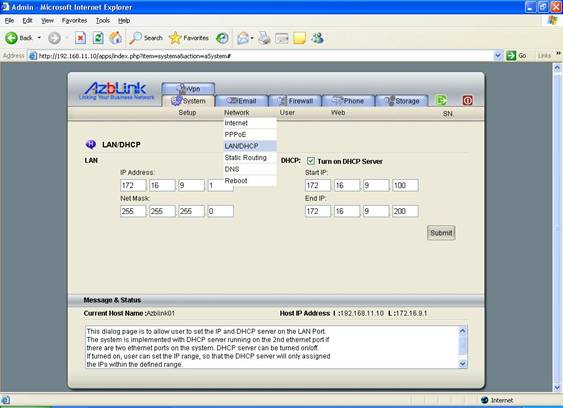
Furthermore, it needs to be very careful when you configure the network. Many people made mistakes by using conflicting address for LAN with respect to outside network. For example, if your outside network is 172.16.9.0/24, your LAN shall be configured by avoiding this class of IP addresses. It is very important to remember this principle to avoid network conflict. This is a common mistake when you are using firewall to separate the network between your office and lab, or deploying a Wireless Access Point into the existing network. This case happens very often when you temporarily put your machine temporarily over an existing network and configure it there and move it to other place. We will elaborate that later.
If DHCP server is not turned on, then the eth1 interface turns on to be an ordinary Ethernet interface. Please notice that DHCP client is not running on this interface eth1 so that it does not fetch the IP address from other DHCP server. If you want to turn off DHCP server on this interface, you always need to make sure that you choose the right IP address for eth1.
There is chance that you might deploy this server into private network to separate the traffic ( Please refer to the case “Separate the traffic between office and lab” in the section “Deployment issues” at the end of this document ). If your machine is with two Ethernet interfaces, during the initial setup, the firewall will be up automatically.
When you set IP address for eth0 and eth1, you have to be carefully without letting them belong to the same network. For example, if eth0 belongs to 192.168.1.0/24, you should not set eth1 to IP address belonging to that network. Instead, you should set eth1 to something else like 172.16.2.1 so that it will not conflict with IP address using by other machine in 192.168.1.0/24.
Static Routing
Static Routing is to specify the associated gateways explicitly for the network traffic to a specific subnet. For example, if traffic to the network 172.16.9.0/24 should go there via 192.168.1.12, then you need to specify it in the routing table so that the traffic can be forwarded to the right place.
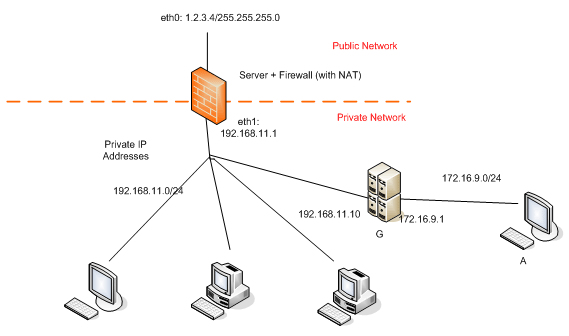
Example: Setting Static Route
In the diagram above, the local network behind the firewall is 192.168.11.0/24. However, there is another network 172.16.9.0/24 behind a gateway G. G is with two Ethernet interfaces: one is with IP 192.168.11.10, the other is with IP belonging to 172.16.9.0/24. Thus, if we want to have the traffic from 192.168.11.1 to travel to the network 172.16.9.0/24 via G, we need to set as follows:
Destination network: 172.16.9.0
Netmask: 255.255.255.0
Gateway: 192.168.11.10
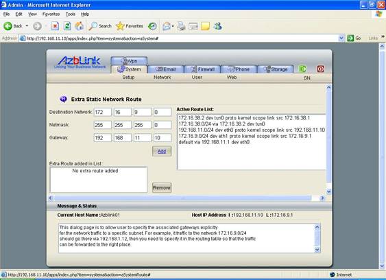
Please notice that this gateway is not “default gateway”; this is the “gateway” to the 172.16.9.0/24 . Furthermore, doing the setting as above does not guarantee your network communication between firewall eth1 and anther server behind the gateway ( denoted as A ) will be running smoothly. It also needs to have the similar setting in A such that it will know the network 192.168.11.0/24 is behind the gateway G correspondingly. As shown in the diagram, host A needs to set its gateway to 192.168.11.0/24 as “172.16.9.1” . So, the traffic from firewall to A can have the correct route for the response packets issued from A. |